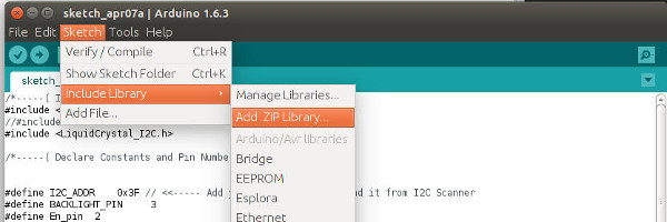
1. Download and install the library
Download the adafruit_GFX library
and the
TFT_ILI9163C library from Github
and add both as shown in this screenshot.
This display comes with a 3V onboard regulator and has (probably) 5V tolerant logic inputs. The backlight "LED" pin goes to 3.3V. For Raspberry Pi operation, bypass the onboard voltage regulator by bridging JP1 with solder as described below.
Download the adafruit_GFX library
and the
TFT_ILI9163C library from Github
and add both as shown in this screenshot.
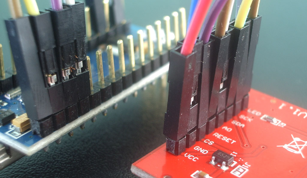
Connect the display in the following way to Arduino Uno, Nano, Pro-mini:
Display pin ---> Arduino pin
VCC ---> 5V
GND ---> GND
CS ---> D10
Reset ---> D12
A0 ---> D9
SDA ---> D11
SCK ---> D13
LED ---> 3.3V
Now copy and paste the following sketch into your arduino IDE:

Your LCD should now display the above text
stay tuned